Hydronic Heating Systems use liquid to radiate heat into the air. An energy source (such as a boiler, water heater, or chiller) heats water that is distributed with a network of pipes to terminal heat-transfer units (radiators) inside designated temperature zones. Electrically-powered pumps circulate the water through a system of insulated pipes that control condensation and limit heat loss. Alternatively, hydronic heating can be used to radiate heat to the floors, where heat will rise to regulate the rest of the room.
Hydronic systems have relatively low initial and operation costs and inaudible operation. Their disadvantage is the lack of humidity control and the inability to offer occupants control over the temperature or ventilation of different zones. Occupied or unoccupied areas are not differentiated. Hybrid systems that combine hydronic and air systems solve this issue.
Types of Hydronic Systems:
Hydronic systems are identified in 5 categories of different operating temperatures by the ASHRAE Handbook (Crall, 2016):
- Low-Temperature Water (LTW): Less than 250°F
- Medium-temperature water (MTW): 250°F to 350°F
- High-temperature water (HTW): Greater than 350°F
- Chilled water (CW): 40°F to 55°F
- Dual-temperature water (DTW): LTW and CW
LTW, CW, or DTW are the most common hydronic systems for commercial building.
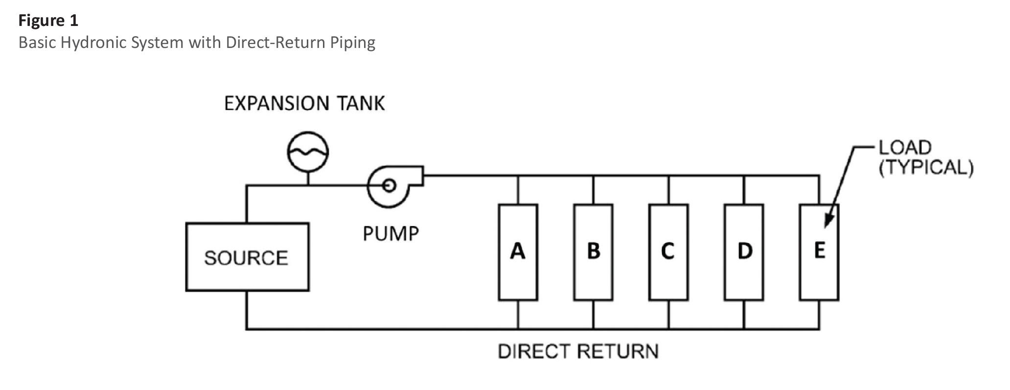 (Crall, 2016)
The figure above represents a basic LTW system with direct return. With a hot-water boiler as the source, heated water is circulated with a pump to heating coils (A through E) located in different temperature regulated zones. An expansion tank is located between the source and the pump to accommodate for the changes in volume caused by temperature changes in the water. This allows the systems pressure to remain relatively constant. The expansion tank and the piping connecting the components in the system are insulated to minimize heat loss or gain to the system.
The piping is either steel or copper. Copper is more expensive but easier to install, easier to bend, and is non-corrosive. Steel is cheaper and used for larger sizes than 1 inch in diameter. Piping systems can be set up for either 'direct-return' or 'reverse-return'. As shown above, the 'direct-return' layout has a shorter flow path for 'Terminal Unit A' than it does for 'Terminal Unit B-E'. This means that the flow rate for 'Terminal Unit A' will be faster than the flow rate for 'Terminal Unit B-E'. Unbalanced flow rates is not ideal. Direct-return systems save on costs of piping material because the minimum distance needs to be covered. However, the flow rates need to balanced across each terminal unit, and balancing valves need to be added.
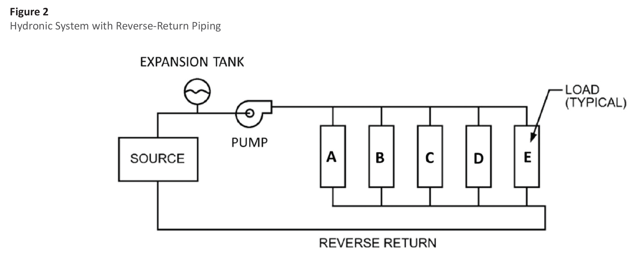 (Crall, 2016)
Figure 2 above represents a similar system with a reverse return instead. The flow path from Pump back to Source is nearly equal so that the flow rate across each Terminal Unit is equal. This allows the system to be self-balancing so that balancing valves are unnecessary. Due to the distance between terminal units generally being longer than what is shown in the example, reverse return systems extra cost in return piping is generally more expensive than the amount spent on balancing valves. However, the extra cost can be worth it when control of the flow rates is important.
Multisource Hydronic Systems:
Hydronic Systems require separate energy source components for heating and cooling the liquid. The way the 2 sources are distributed to each load can be a 2 or 4 pipe system.
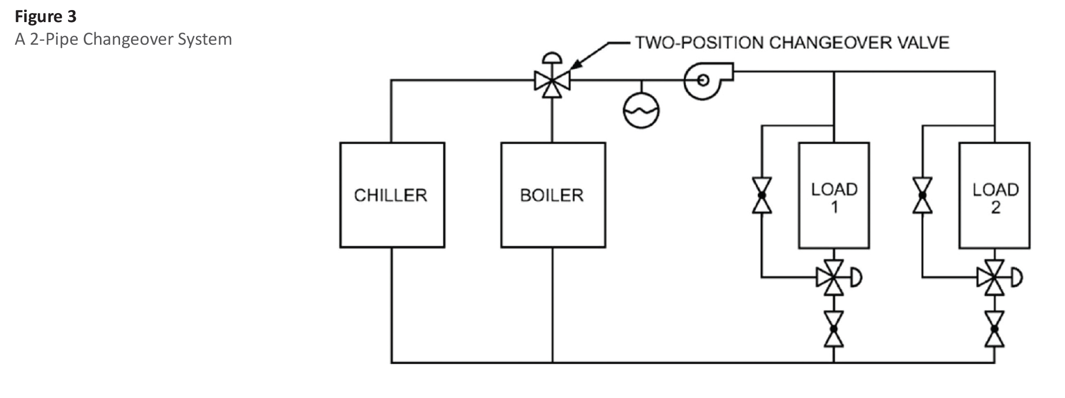 (Crall, 2016)
Figure 3 shows a 2-pipe system where the system can only supply either cold water or hot water. This is controlled by a single changeover valve that decides which energy source supplies liquid to the pump. With a 2-pipe system, seasons in between summer and winter where temperatures are more moderate will not be able to regulate each load (terminal unit) accordingly since the system can only be in heating or cooling. If one room is hotter than the setpoint while another room is colder than the setpoint, a system in cooling mode will cool down the hotter load while over-cooling down the colder load as well.
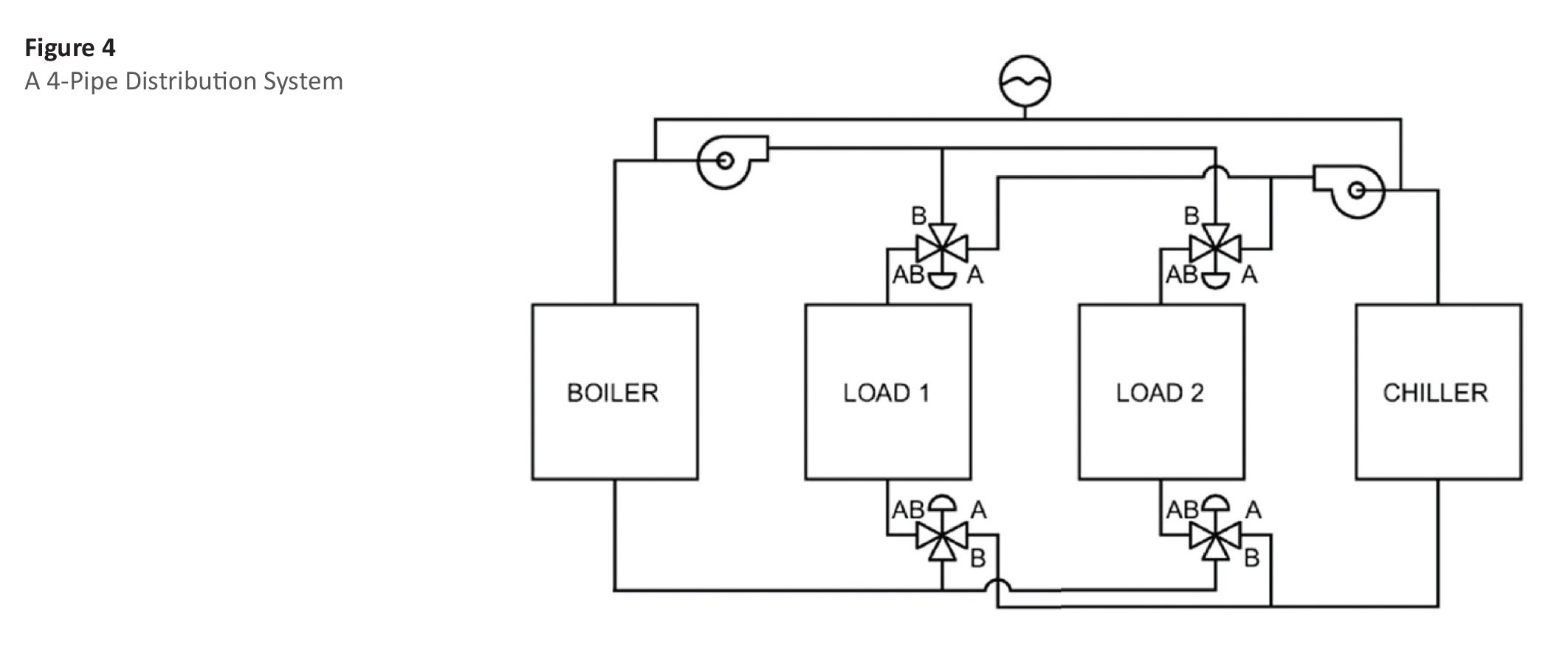
(Crall, 2016)
Figure 4 represents a 4-pipe hydronic system with both a boiler and a chiller source. A 4 pipe system give the option to circulate either heated and chilled water at the same time to accommodate what is needed at each individual load (terminal unit). In the system, there are separate supply and return pipes for each energy source. Each supply pipe also has its own pump. Each load (terminal unit) has its own changeover valves connected to both supply pipes and both return pipes. The additional piping and components make the system much more expensive, but result in more comfortable occupants (especially in intermediate months).
Insulation:
Standard insulation used in hydronic systems were created in the 2015 International Energy Conservation code (IECC) (Crall, 2016). For chilled water lines. the IECC requires piping smaller than 8" NPS (Nominal Pipe Size) to have insulations between 1/2-inch and 1-inch thick. For hot water lines below 200 degrees Fahrenheit, IECC requires insulatuion between 1-inch and 2-inches thick. Exceptions are made for piping locations where the energy loss from the lack of insulation would benefit the heating or cooling of the space that the pipe is located in. For example, if a hot water pipe is running through a space that is always heated anyway, insulation is not necessary.
Different materials are used for insulation in hydronic systems including:
- Mineral fiber insulation such as fiber glass or mineral wool, along with a factory attached all-service jacket is commonly used in commercial buildings for both hot and cold pipe
- Flexible elastomeric and polyolefin isolations without any jacketing are common
- Polyisocyanurate, phenolic, extruded polystyrene, and cellular glass insulations are also used
Terminal Units:
There are many different types of terminal units that are used in hydronic systems. These include finned-tube radiators, central air-handlers with heating/cooling coils, zone reheat coils, convectors, unit heaters, fan-coil units, radiant heating/cooling panels, and water-to-water- heat exchangers (Crall, 2016). The most straightforward terminal units are the finned-tube radiators. Hot or cold water runs through the pipe while air dampers adjust the airflow across the finned metal coils connected to the pipe.
 Finned Tube Radiator (Engineered Air, 2020)
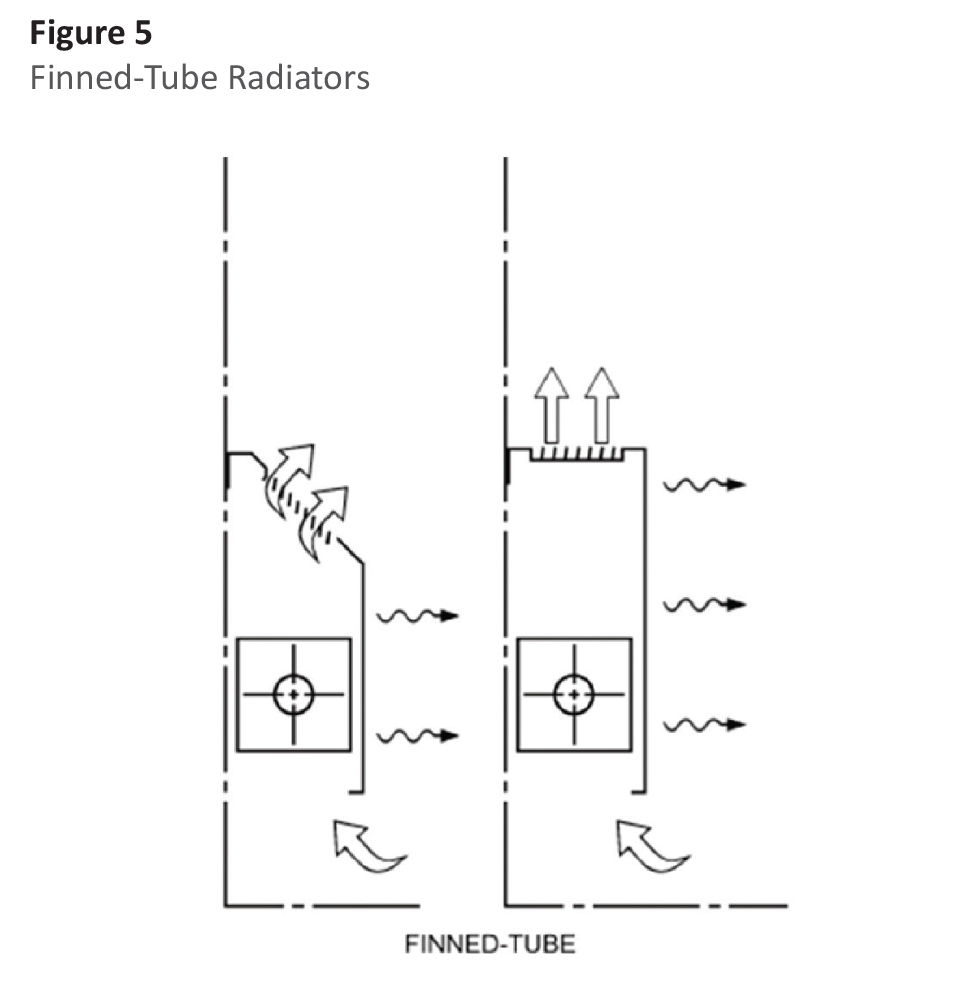
(Crall, 2016)
Fan coil units are also extremely common in hydronic systems. Fan coils use electric powered fans to control airflow across heating/cooling coils. The heating and cooling coils inside of the fan coils are most likely finned-tube coils as well. Since there are 2 separate coils for heating and cooling, a 4-pipe system is usually paired with fan-coils. Generally, the return air opening is nearby, but not enclosed/directly attached to ductwork coming from a central air handling unit. This return air to come from both inside the regulated zone as well as fresh air coming from the air handler. For further information on how fan coils work with air handlers, watch the following video:
Individual thermostats are used to monitor zone temperature that then varies the fan speed within the fan coil to regulate the temperature.
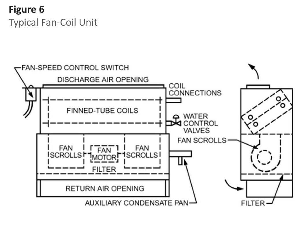
(Crall, 2016)
References:
BigRentz. (2022, April 21). 8 Common Types of HVAC Systems and How They Work. BigRentz. Retrieved January 4, 2023, from https://www.bigrentz.com/blog/types-of-hvac-systems
Crall, C. P. (2016, October 25). Understanding Thermal Systems: Hydronic Heating And Cooling Systems. Insulation Outlook Magazine. Retrieved January 5, 2023, from https://insulation.org/io/articles/understanding-thermal-systems-hydronic-heating-and-cooling-systems/#:~:text=Hydronic%20systems%20consist%20of%20an,units%20located%20in%20the%20spaces.
Finned Tube Radiation Solutions. Engineered Air | One of North America's largest fully integrated manufacturers of made-to-order heating, ventilating, air conditioning, refrigeration and energy recovery equipment. (2020). Retrieved January 9, 2023, from https://www.engineeredair.com/index.php/our_products/category/heat-transfer
Admin
Comments